RF Capacitance vs RF Admittance Level Sensor
By Megha Parolkar on March 22, 2019
BeginnerIntroduction
Level sensor operates on distinct technologies such as Vibrating Fork, Capacitive, RF Admittance, Conductive and Electromechanical. This article enlightens the principle and designing of Capacitive and RF Admittance Level Sensor. While both the principles rely on Capacitance Measurement, RF Admittance Level Sensors have been superior in applications with heavy build-up.
How RF Capacitance Level Sensors Work?
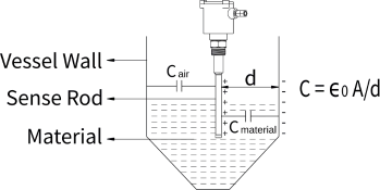
Capacitance is formed between the level sensing probe and metallic wall of the vessel which act as two electrodes, and the application media acts as a dielectric medium when the sensor is introduced into the vessel. These electrodes are separated by an insulator by suitable media like solid and liquid known as a dielectric medium. The dielectric is the main factor in the capacitance principle as its value will be influenced by temperature and moisture content of operating material. These factors should be taken into account while designing the probe.
When the level of process material rises, the value of dielectric changes which results in change in the value of capacitance between the level sensing probe and the vessel wall. This change can be detected and measured by the Radio Frequency technique. These RF signals are interpreted by the evaluation unit and it converts these signals into a relay output signals. RF current flowing in the capacitor helps the electronics detect the presence of application media.
Probe Design
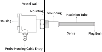
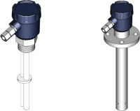
The design of the probe comprises of sense rod and grounding part. The probe can be made of stainless steel which resists stains and corrosion and gives rigid support to the level sensor. The design of the probe can be varied with tank type and application media. The probe design for various tank types and materials are given below:
- Metallic Tank - Metallic tanks act as a ground in which only the sensor rod is sufficient without any reference and grounding.
- Non-metallic Tank - The non-metallic tank requires a reference probe for proper grounding which is possible by the following arrangements:
- Twin Probe - It provides appropriate grounding for material having low pf value with reference and sense rod.
- Still Well - It gives proper grounding for material having low dielectric media and creates turbulence by providing ground over sense rod.
Electronics Design
Based on electronics, capacitance based level sensors are categorized into two parts:
- Level Switch - The point level switches are used to detect the presence of material at a predefined level. When the material is reached at that particular level then it produces an alarm condition to prevent overflow.
- Level Transmitter - The level transmitter is designed for continuous level measurement of material at any certain period of time. It continuously monitors the material level throughout the process.
Limitations
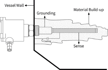
Build-up on the capacitance probe can cause the capacitance sensor to malfunction. The capacitance level sensor starts giving a false alarm when material sticks on the probe.
Comparison between Capacitive Level Sensors
| Products | SLC | Capvel-ICT | Capvel-LP | Capvel-FUEL | MPILC |
|---|---|---|---|---|---|
| ProductType | Level Switch | Level Transmitter | Level Transmitter | Level Transmitter | Level Transmitter |
| Probe Length | 100mm to 20m | 100mm to 10m | 100mm to 10m | 100mm to 2000mm | 100mm to 10m |
| Application Media | Free-flowing Solid/Liquid | Free-flowing Solid/Liquid | Free-flowing Liquid | Fuel | Free-flowing Solid/Liquid |
| Response Time | 2-3 Sec | 2-3 Sec | 2-3 Sec | 8 Sec | 2-3 Sec |
| Output | Single-Point,Two Point, Three-Point Switching and Pump Control Logic | 4-20mA Voltage Analog Output,Digital Output (RS-485), PNP Output | 4-20mA | 0.2-5V voltage Output,Digital Output (RS-485, RS-232), Fuel Guage Analog Output | 4-20mA,Voltage Analog Output, Three Point Relay Output |
How RF Admittance Level Sensors Work?
In this principle, the sense electrode and the vessel wall act as two electrodes of a capacitor and a material "shield" is proposed as an insulated electrode that will be added between ground and sense part. The sense and the shield are connected to the same source but they are electrically isolated from each other. Due to this, no RF current is flowing between the shield and the sense electrode. The main purpose of adding a shield is to block the RF current from reaching the vessel wall via the coating of the probe.
The sense probe and the shield are maintained at equipotential which prevents the flow of RF current from the probe to the vessel wall while having build-up on the probe and when actual material touches the probe the RF current starts flowing. This design helps the electronic circuitry to differentiate between build-up and the real material. As the level of the vessel increases, the dielectric changes which inturn causes a change in admittance. This change inadmittance correctly measured by RF technique.
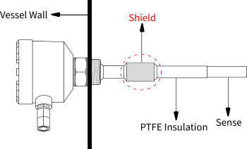
Probe Design


Electronics Design
Comparison between Admittance Level Sensors
| Products | SLA Dot Display | SLA Bar Display | SLA Series | Coat Endure |
|---|---|---|---|---|
| Type | Integral and Remote Model | Remote Model | Integral and Split Model | Compact & Integral |
| Probe Length | 150mm to 10m | 150mm to 10m | 150mm to 10m | 65mm to 150mm |
| Application Media | Non-conductive Sticky Media | Non-conductive Sticky Media | Non-conductive Sticky Media | Conductive & Non-conductive Sticky Media |
| Response Time | 2-3 Sec | 2-3 Sec | 2-3 Sec | 1-3 Sec |
| Output | Single Point Switching | Single Point Switching | Single-Point,Two Point, Three-Point Switching and Pump Control Logic | Single Point Switching |
Factors for Protection Purpose
- PTFE Insulation
- Ceramic Insulation
More articles on Intro Level Sensor